BEFORE
YOU BEGIN
Customer
Service
If you need assistance, the Newport Electronics Customer Service Department
is available at 714-540-4914 from 7:00am until 5:00pm Pacific Standard
Time.
Inspecting Your Shipment
Remove the packing slip and verify that you have received everything listed,
including:
1 IDT indicator/controller with all applicable connectors attached
1 IDT Owner's Manual
Note: If you ordered any of the available options (except the "BL"
blank Lens option), they will be shipped in a separate container to avoid
any damage to your indicator/controller.
 Warning: Inspect the container and equipment for signs of damage as
soon as you receive the shipment. Note any evidence of rough handling
in transit. Immediately report any damage to the shipping agent. The carrier
will not honor damage claims unless all shipping material is saved for
inspection. After examining and removing the contents, save the packing
material and carton in the event reshipment is necessary.
Warning: Inspect the container and equipment for signs of damage as
soon as you receive the shipment. Note any evidence of rough handling
in transit. Immediately report any damage to the shipping agent. The carrier
will not honor damage claims unless all shipping material is saved for
inspection. After examining and removing the contents, save the packing
material and carton in the event reshipment is necessary.
What You Will Need
In addition to the meter and connectors, you will need the following items
to setup your unit:
115VAC three-prong power cord
1 /8" flat head screwdriver
Features
and Options
Basic Features
Your meter has several basic features, some of which are listed below.
For more detailed information on specifications and factory defaults,
see Part 3: Defaults & Specifications.
* 4 digit, 7 segment LED display with programmable decimal point
* Nonvolatile memory-no battery backup necessary
* 115Vac or 230Vac 50/60 Hz power source
IDT
Options
The IDT unit is available with an optional NEMA-4 front panel cover. Please
contact Newport Customer Service for a list of additional products and
accessories.
Safety
Considerations
The IDT is protected in accordance with Class II of IEC 348 and VDE 0411.
Remember that the unit has no power-on switch. It will be in operation
as soon as you connect it to a power source.
Warning:
Do not expose the unit to rain or moisture. Do not operate your unit in
flammable or explosive atmospheres. As with any electronic instrument,
you may encounter high voltage exposure when installing, calibrating,
or removing parts. Be careful when working near conductors carrying large
currents. Use twisted-pair connections to the unit. Use magnetic shielding
materials, or move the unit away from the current source to reduce magnetic
field problems. Do not exceed power rating on label located on the top
of the controller housing. Failure to follow all instructions and warnings
may result in injury!
Getting
Started
Follow these steps to start using your unit right away:
1. Mount the unit
2. Connect Sensor Input
3. Connect the AC power cord
4. Turn on the unit
Mount
the Unit
1. Remove the two nuts at the back of the unit, which hold the
mounting sleeve. Remove the sleeve.
2. Cut a hole in your panel, as shown.
3.
Insert the unit into the hole. Be sure the front bezel is flush to your
panel. Slide on the mounting sleeve from the rear of the panel and tighten
the unit until snug, using the two nuts.
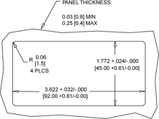
Figure 1.1
Panel Cut-out Dimensions
|
|
Connect
Sensor Input
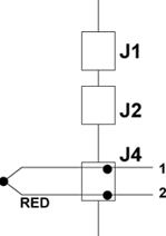
Figure 1.3 Thermocouple Input Connection
Connect
the AC Power Cord
1. Locate the connector pins. (see Figure 3.1)
Warning: Do not connect AC power to your unit until all input
and output connections have been properly established. Failure to do
so may result in injury.
2. Insert the correct wire in each terminal and tighten the lockdown
screw. See Table 1.1 for wire color definitions. Tug gently on the wires
to verify that the connections are secure.
|
AC
POWER
|
WIRE
COLORS
|
|
|
EUROPE
|
USA
|
|
AC-High
|
Brown
|
Black
|
|
AC-Low
|
Blue
|
White
|
|
AC
-Ground
|
Green/Yellow
|
Green
|
AC Power Wire
Color & Connections Table
1.1
Turn
On the Unit
1. Plug the unit into a properly grounded 115V power supply. The
unit will initialize, scrolling the following three messages on the front
panel:
(r
0 I equals the
revision code of the
micro controller. Keep
track of the revision
code for future reference.)
2. The present value of the Thermocouple should be displayed. If
a value is not displayed, follow these steps:
- Unplug the unit
- Verify the power
and TC connections
- Check your power
source
- Plug
the unit in again
|